
Clay Brick Plant Layout Design: Zones, Flow and Planning

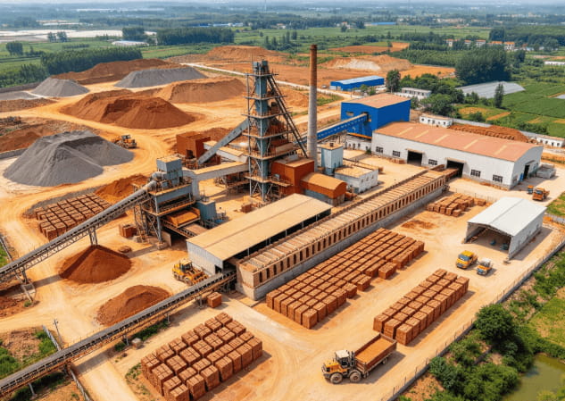
Clay brick plant layout design arranges production zones, equipment, transport routes, and utilities into a workable manufacturing system. A suitable layout supports consistent material flow while allowing space for drying, firing, maintenance, storage, and dispatch.
The shortest conveyor route does not always produce the best operating arrangement. A compact drawing can hide restricted maintenance access, insufficient buffer capacity, or repeated crossings between loaders and finished-product traffic.
Start with the product range, tested clay behavior, and target saleable output. Then compare layout options against those operating requirements before fixing building dimensions and foundations.
What Zones Should a Clay Brick Plant Include?
The main production zones follow the manufacturing sequence, but supporting areas need equal attention. Workshops, electrical rooms, environmental equipment, and access roads should appear on the initial site plan.
The Brick Industry Association’s manufacturing guidanceidentifies stages from raw-material storage through preparation, forming, drying, firing, and finished-product storage. The following table translates that sequence into practical layout considerations.
| Plant zone | Typical equipment or activity | Layout priority |
|---|---|---|
| Raw-material receiving and storage | Unloading, separate stockpiles, blending | Loader access, drainage, and material identification |
| Clay preparation | Feeders, crushers, screens, mixers | Transfer alignment, dust control, and service access |
| Forming and cutting | Extruder, die, cutter, handling system | Supported transfers and room for tooling changes |
| Drying | Chambers, tunnel dryer, racks, or kiln cars | Loading access, circulation, and controlled waiting areas |
| Firing and cooling | Kiln, burners, fans, ducts, handling equipment | Thermal connections and operating clearances |
| Inspection and packing | Sorting, sampling, strapping, pallet handling | Separation of accepted, held, and rejected products |
| Finished-product yard | Storage lanes and truck loading | Dispatch access and stock traceability |
| Supporting services | Workshop, utilities, fuel and emissions equipment | Maintenance routes and appropriate separation |
Raw-material storage should accommodate the intended blending method. Separate bays may be needed when different clay sources or additives require controlled dosing.
Provide a defined route for production rejects. Unfired material and fired rejects may require different treatment, so they should not share an uncontrolled return stream.
How Should Equipment Flow Connect the Production Zones?
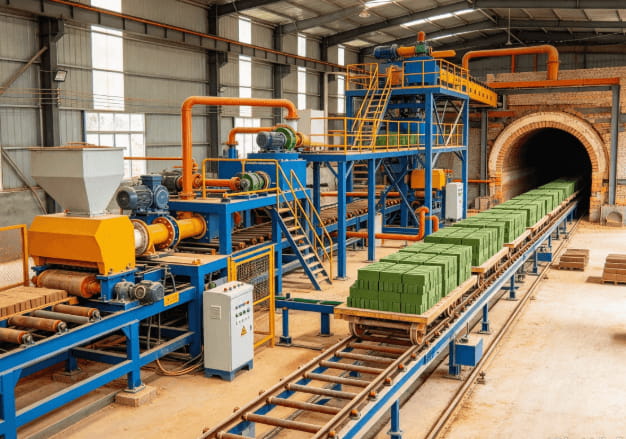
A layout needs to show how material moves between machines, including changes in elevation, orientation, support, and transport method. Equipment footprints alone cannot establish whether those transfers will work.
For a typical extruded line, review these connections:
- Storage to preparation: Confirm feeder access, conveyor elevations, and the route for oversized material.
- Preparation to extrusion: Match feed consistency and delivery capacity to the forming equipment.
- Cutting to drying: Define how soft bricks are supported, grouped, and transported.
- Drying to firing: Check transfer equipment, loading arrangements, and kiln entry requirements.
- Cooling to packing: Allow inspection, sorting, and removal of nonconforming products.
- Packing to dispatch: Keep loading activity from obstructing production movements.
For the underlying manufacturing stages, see Clay Brick Production Process: From Raw Material to Firing.
Decide the handling method before positioning the dryer
Some plants dry bricks on racks before setting them onto kiln cars. Others can place sufficiently stiff green bricks directly onto kiln cars for drying.
The Brick Development Association’s brickmaking guide describes both arrangements. It explains that dryer selection depends on clay, forming method, product type, and process flow.
This choice changes the required transfer stations, return routes, and loading space. Confirm green-brick handling strength through trials before adopting a layout that depends on direct setting.
Balance operating schedules, not just machine capacities
Forming equipment may operate fewer hours than a continuously running kiln. The layout therefore needs a defined way to accommodate their different schedules.
As an illustrative calculation, 100,000 saleable bricks at a 95% overall saleable yield require approximately 105,300 formed units. These figures are planning assumptions, not recommended performance targets.
Translate that requirement into equipment operating hours, drying loads, kiln occupancy, and packing shifts. Compare capacities using the actual brick geometry rather than an undefined “standard brick” equivalent.
Dryer assessment should also consider water evaporation duty. Two products with similar daily piece counts can impose different drying demands.
Clay Brick Plant Layout Design for New and Existing Sites
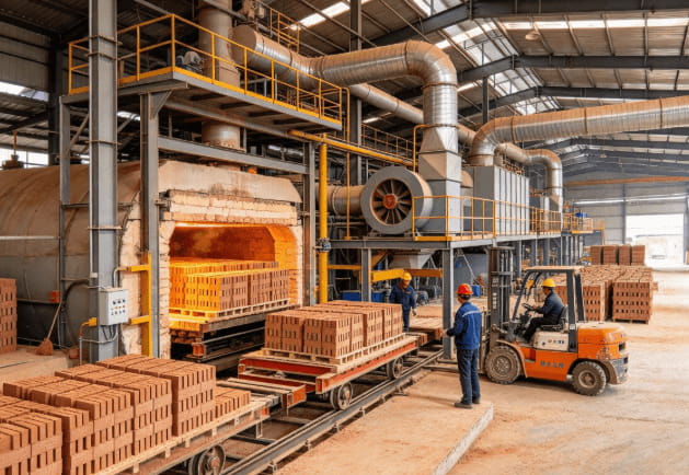
A new site offers more freedom to arrange buildings and transport routes. An existing factory usually requires compromises around fixed foundations, utilities, access gates, and production continuity.
Compare the options using the same product mix, output basis, and equipment scope.
| Arrangement | Where it may fit | Main tradeoff to examine |
|---|---|---|
| Straight-through flow | Elongated sites with suitable receiving and dispatch access | Longer buildings and return routes |
| Parallel production blocks | Wider sites or phased development | More transfer points and coordinated crossings |
| Folded flow | Restricted plots or existing buildings | Congestion around turns and shared handling areas |
| Circular kiln arrangement | Projects using a compatible moving-kiln system | Radial access, service connections, and loading geometry |
These are screening options rather than standard designs. A folded arrangement may shorten the building while increasing handling complexity.
Protect production from site traffic
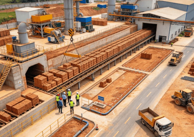
Show raw-material deliveries, loader movements, forklifts, dispatch trucks, and pedestrian routes as separate flows. Pay particular attention to intersections near packing stations and kiln access points.
The UK HSE’s site layout and internal traffic route checklist emphasizes suitable routes, pedestrian separation, crossings, and visitor access. Use these principles alongside applicable local requirements.
Check turning movements with the intended vehicles. A road that accommodates a forklift may still restrict an articulated delivery truck.
Plan expansion as a connected route
Leaving an empty corner does not establish expansion capacity. A second line needs access to raw materials, utilities, drying, firing, packing, and dispatch.
For an operating factory, identify construction access and equipment installation routes before selecting the expansion area. Otherwise, new works may interrupt the line they are intended to support.
Review drainage and ground conditions alongside the building arrangement. Low areas, buried services, and unsuitable bearing conditions can change foundation and road costs substantially.
Evaluate the Layout Before Fixing Foundations
A useful layout review asks operators and maintenance staff to walk through routine tasks on the drawing. Include blocked conveyors, die replacement, fan servicing, kiln maintenance, and product changeovers.
Check the following before releasing the arrangement for detailed engineering:
- Equipment footprints, elevations, and foundation loads.
- Maintenance envelopes and component removal routes.
- Buffer locations and their intended operating purpose.
- Empty-car, rack, pallet, and packaging return routes.
- Fuel delivery, utility connections, and isolation access.
- Dust collection, emissions equipment, and service space.
- Finished-stock capacity based on dispatch patterns.
Keep production flow and thermal connections on coordinated drawings. The BDA guide describes recovery of kiln cooling heat for dryers, making duct routing relevant to equipment placement.
Shorter ducts may reduce distribution losses, but access, pressure requirements, and temperature control still need assessment. Dryer proximity alone does not establish an effective heat-recovery system.
Yaxin’s Prefabricated Tunnel Kilnpage describes modular construction, kiln-car tracks, drying sections, and digital firing control. For layout evaluation, confirm track spacing, transfer areas, duct connections, and maintenance clearances for the proposed configuration.
Its Mobile Rotary Tunnel Kiln uses circular rails and describes connected drying, preheating, firing, and cooling sections. This configuration requires a different spatial review from a conventional straight tunnel kiln.
Compare the complete installed arrangement, including services and handling areas. A smaller kiln footprint may not mean a smaller total factory site.
FAQ
How much land does a clay brick plant need?
There is no reliable universal area per daily brick capacity. Product dimensions, storage duration, drying method, kiln configuration, roads, and expansion requirements all influence the site area.
Should the extruder, dryer, and kiln have identical hourly capacities?
They need compatible production schedules rather than identical nameplate ratings. Account for operating hours, product changes, downtime, yield, and planned buffer capacity.
Can an existing building accommodate a new brick production line?
Possibly, but floor area is only one constraint. Check clear height, structural loads, transfer elevations, maintenance access, ventilation, and vehicle movements before accepting the arrangement.